2nd User Port
Back in the day I never really used the user port. One of the early
Soldisk SWR boards used it (to enable write access ?&FE62=15: ?&FE60=slot),
but later ones did it properly.
In this modern day it seems lots of people have created things that use
it. In my case I have a
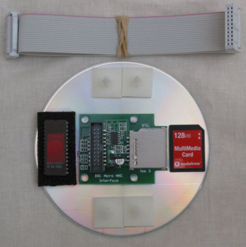
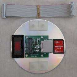 TurboMMC board from Steve Picton
and a UPURS
cable. Both need the user port so, of course, both can't be used
at the same time. My first attempt to work around this was a switch
box. Basically I kludged a 25-pin bi-directional parallel switch box
into acting like a user port switch box. It works for this use case;
I can switch between UPURSFS and MMC by pressing the right button
and then control-break.
TurboMMC board from Steve Picton
and a UPURS
cable. Both need the user port so, of course, both can't be used
at the same time. My first attempt to work around this was a switch
box. Basically I kludged a 25-pin bi-directional parallel switch box
into acting like a user port switch box. It works for this use case;
I can switch between UPURSFS and MMC by pressing the right button
and then control-break.
Can I do better? The fine folks on the *. forums convinced me to make an attempt.
In an early edition of The Micro User (August 1984) there was an
article by Mike Cook where this very question was addressed. There was
even a 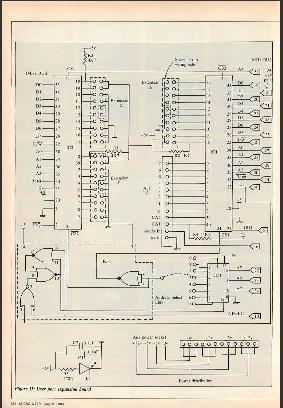 schematic for an
expansion board that created 4 new user ports! (click on image for a
larger version)
schematic for an
expansion board that created 4 new user ports! (click on image for a
larger version)
Obviously they aren't
mapped to the same memory location so "out of the box" software won't
find them, but software can be hacked...
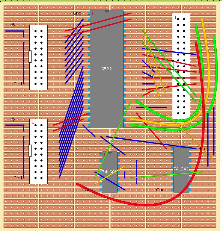
I didn't need 4 ports. I tried something simpler; 2 ports. This
requires a 6522, a 74LS02, a 74LS42, some sockets and a lot of soldering.
Have I mentioned that I have the soldering skills of a demented monkey
on crack? Well, this would help me learn...
After a few attempts (including totally getting the pin numbers wrong)
I came up with
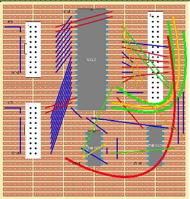 this design. (click for a larger version)
I don't have the power or ground pins connected up, but everything else
should work. In theory this is the left-hand side of the original
schematic, so should provide extensions "B" and "C" of the diagram.
I also hard-linked the device to pin 1 of the 74LS42; this will cause
the two ports to appear at base &FC10 and &FC11.
Another change; I didn't add pull-up resisters to CA1 and CA2 (pins 18 and
40 of the 6522) because the schematics in the original userguide (appendix
K) and the Advanced User Guide (insert) didn't have them. I'm not sure
why Mike Cook felt they were necessary. Hmm.
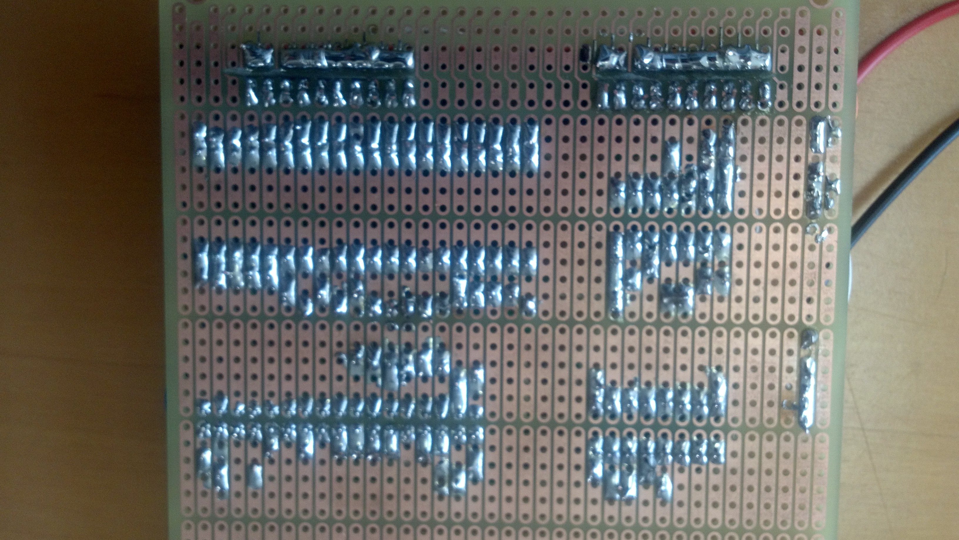
A few attempts later (3 attempts, as it happens; one including ripping
copper traces off the veroboard in an attempt to desolder!) I managed
to put a board together.
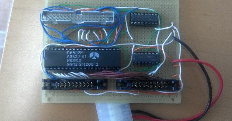

Simple tests (setting output pins, seeing them go to 1; reading input and
grounding them) showed good results. The question, though, is how well it
works for real world stuff?
So I took my HostFS:UPURS source code and
made a small modification:
\ These values are for the User Port
\ upiob   = $FE60   \ I/O Register B
\ upddrb  = $FE62  \ Data Direction Register B
\ upacr   = $FE6B   \ Auxilliary Control Register

\ These values are for the 2nd User Port at FC10
upiob   = $FC10   \ I/O Register B
upddrb  = $FC12  \ Data Direction Register B
upacr   = $FC1B   \ Auxilliary Control Register
Quick assemble and copy the code over. Plug it in and...
IT WORKED!
Wow, I made something :-)
Last modified: Friday, 04-Oct-2013 16:31:38 EDT
 TurboMMC board from Steve Picton
and a UPURS
cable. Both need the user port so, of course, both can't be used
at the same time. My first attempt to work around this was a switch
box. Basically I kludged a 25-pin bi-directional parallel switch box
into acting like a user port switch box. It works for this use case;
I can switch between UPURSFS and MMC by pressing the right button
and then control-break.
TurboMMC board from Steve Picton
and a UPURS
cable. Both need the user port so, of course, both can't be used
at the same time. My first attempt to work around this was a switch
box. Basically I kludged a 25-pin bi-directional parallel switch box
into acting like a user port switch box. It works for this use case;
I can switch between UPURSFS and MMC by pressing the right button
and then control-break.